What Wiring Should I Choose For a Resistance Temperature Detector?
Resistance Temperature Detectors (RTD) are connected to the measuring instrumentation using any one of three different connection principles:
- Two wire, with no lead wire compensation
- Three wire with partial compensation
- Four wire with full compensation.
Two wire connection is the simplest wiring method. Since the variable output of an RTD is resistance, it follows that the resistance of the connecting leads (L1 and L2) between detector and instrument will also have an impact on the final measurement, and therefore the temperature inferred at the detector.
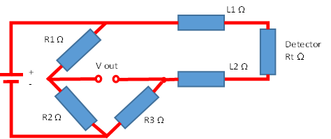
Where the lead lengths are short, and where they are exposed to the same temperature as the detector, then in theory this can be accounted for.
For PT1000 detectors, which have a much greater resistance change per temperature increment, a 2 wire connection may be satisfactory.
However in, for example, a Pharmaceutical autoclave chamber, where the lead length between probe and instrument can be very long, a two wire connection would lead to significant measurement error.
A high proportion of the leads will be inside the chamber during the sterilising cycle, and therefore at the same elevated temperature as the detector. The remaining lead length will be outside the chamber and at ambient temperature. These temperature differences will cause resistance change in the lead wire conductors.
The 3 wire compensation method was adopted using a modified Wheatstone bridge.
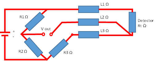
In this configuration the detector lead wires L1 and L3 are connected to the opposite sides of the bridge, effectively compensating for each other, with the third wire L2 supplying power to the bridge.
However this will produce a thermal gradient along the leads themselves. Although the effect of Joule heating is reduced, it cannot be eliminated altogether because the heat transfer conditions at the detector will be different from those of the matching 100Ω resistor in the bridge circuit. In fact there will only be one situation when this effect is eliminated entirely and that is when both the 100Ω resistor and the PT100 detector are at the same temperature.
The 4 wire system was developed to enable more accurate measurements to be made, particularly when the connecting lead wires are relatively long and passing through varying ambient temperatures.
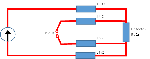
One pair of lead wires takes the constant current power source to the detector and the other pair is used to measure the actual voltage drop across the detector. Therefore by using a constant current source and being able to simply measure the change in voltage across the PT100 detector rather than a change in resistance (Ohms Law), any fixed or varying lead wire resistance is totally eliminated.
The realistic choice for a PT100 probe is therefore between a 3 and 4 wire system, and the user may be constrained by the limitations of existing instrumentation that may already be in place.
Thermal Detection would recommend using a 4 wire system where possible, to ensure the most accurate reading. The use of a 3 or 4 wire PT100 temperature transmitter is a further option to reduce the overall lead length and convert the probe reading to a 4-20mA signal which will be easily integrated into process instrumentation.